Haxing and Technology

A place for various hacks and technology related posts such as: Gentoo, my Battle Station, hardware hax, and hacking ideas.

I am a hardcore GNU/Linux (Linux) user and a fan of tiling windows managers such as xmonad. I have been running Linux as a desktop OS since 2004, first starting with LinuxPPC in 1999. While I have used many different distros, Gentoo remains my favorite, followed by Debian, Arch, Mint, Ubuntu, and Slackware. I really enjoyed Slackware when I ran it on the old Pentium I had in the trunk of my Impala, but that was a long time ago. Ubuntu has always been easy to get running, but hard for me to keep stable, Mint ran amazing when I last used it, but Debian and Arch became two of my go to distros.

Gentoo, requiring one to compile from code using the emerge command, I’ve usually kept for my more powerful and newer computers. The exception has been Gentoo on my Odroid U3 and Lenovo S10 Netbooks, both were surprisingly smooth to compile to X. Gentoo has been my main desktop due to it’s overall stability and powerful update capabilities with emerge. I custom build all my Gentoo systems, crafting the make.conf and various portage configuration files for the main purpose of the system. My average Gentoo system will run for over 200 days without a reboot, but I don’t know for fact how long they’re run as power outages or major upgrades have required reboots.

In addition to building stable systems, I customize my interfaces to my exact usage and needs. I prefer a clean interface, minimal clutter, lots of keyboard shortcuts, customized status icons and windows, and having windows in their exact places. In the past I would install Windowmaker or XFCE, but xmonad has become my favorite. I’ve run KDE, Gnome, Mate, Openbox, IceWM, etc, but until xmonad, I would always witch back to XFCE.

My personal desktop is a triple head intel core2quad with 16gb of ram, a nvidia 8800GTS and 295GTX video cards. In most OSes and window managers windows often pop open on the wrong screen, then repositioning them exactly as I would like became an excessive exercise for my right wrist. In 2013, prior to my move to South Florida, I started running xmonad alongside XFCE, and fell in love.

Due to the move to SoFla, not having a permanent room for nearly six months, some minor hardware failures ,and a new hard drive, I didn’t  reconfigure my xmonad install, plus I was using Macs at my new job. My Linux desktop became a hackintosh for a couple of years before I restored my Linux OS. Macintosh is next preferred OS after Linux, so I was okay with running a Hackintosh. I also had Gentoo running on my Lenovo Y510P hacking laptop, so I wasn’t without my Linux fix. Part way through 2015 I felt it was time to put my desktop back on Linux, so I recovered my Gentoo install and used XFCE for a while.

Fast forward to spring 2017. During March I avoided computers, except for work and necessary research. Come April I’m back on my Gentoo desktop, itching to reinstall xmonad and recover my old configuration, so I did.

Gentoo made the xmonad install quick and easy, but my old config file had mistakes in it that I never noticed in 2013. Xmonad has what are called layouts, basically grids for how you want the screen you are using to be laid out. A proper laytout can ever define where in the grid certain application windows should display and at what size. You update your layouts in a configuration file, maybe important layout definition files, then recompile and relaunch xmonad to load the new layouts. I would update my layouts in the config file, recompile successfully, but I would cycle through the same four default layouts.

I eventually discovered typos in the config file, plus mine was using older syntax, not taking advantage of updates to the syntax. I started picking my old configuration apart, rewriting pieces into a new configuration file following current standards. This worked, my xmonad config now switched between many layouts that I had never seen before. Suddenly computer stress lessened, these layouts were perfect for me.

I have a full screen layout, one that does split screen, another that I use to accordion multiple terminal windows into my portrait display, and circular layout that puts the main window in the center, and even a full screen that has tabs to let me switch which window is full screened.

Now that I have base layouts that I love loading, I can start working on app specific layouts. These are used primarily for things such as positioning your IM buddy list on a specific screen in a specific location, with the specified size. My plan is to have one layout for my cryptocurrency wallets, another for my IDE, one for my media player, status monitoring apps, etc.

It will take some time to get this all setup, plus there are other tasks to accomplish. I probably won’t finish these customizations for months, they’re a low priority now that the base layouts are working.  One has to balance their tasks and house repairs are top of my list, followed by bus and fleet repairs, and normal life. It feels good to have my Linux GUI set back up the way it should be. This may sound odd, but a customized OS simplifies and reduces stress in my life.
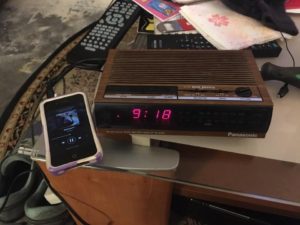
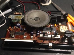
The Panasonic RC-6064 is an AM/FM clock-radio produced in the late 80s and early 90s. This one I received as a Christmas gift in 1989 and has served me well over the past 28 years. A few years ago I tried to replace it with a newer clock-radio that had an iPod dock. The blue lights from the new clock-radio keep me up at night, so it was time to switch back. Two things my childhood clock-radio always needed was aux-in and an external FM antenna. Thanks to the chipset diagrams available online I was able to figure where I could mod the circuit to add these.

Aux-In

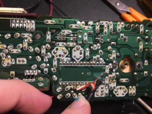
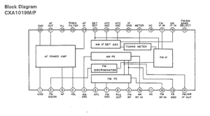
The clock-radio uses a Sony CXA1019P IC (IC2 on the board), an AM/FM IC with built in power amp. By tapping into the AF in pin (pin 24) for the power amplifier, I was able to wire a 3.5 mm (1/8th) headphone jack directly in.

Sony CXA1019 IC Diagram

R and L aux-in soldered to the AF In pin and the ground wire soldered to ground on the IC.

External Antenna

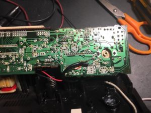
The external antenna took a little bit more work to figure out. I had to figure out where in the circuit I could tap an antenna into. Using circuit diagrams I found in a google search I was able to discern that the antenna circuit should come off of the FM RF in pin (pin 12). From there I used a test lead on a weak station to identify the ideal spot on the circuit board to solder the antenna lead to. I ended up following the traces and found an unused hole immediately in front of the radio/alarm on/off switch. I was able to wire the lead to there and ran it out through the back of the case.

The external antenna starts off as the small black wire in front of the left slider switch

The wire is soldered to the antenna circuit which happens to have a trace running along the top of the board in this photo

Final Results

It is all working. The aux-in works great with my various audio players and cell phones, the external FM antenna helps me to better pull in the public radio station I enjoy listening to.


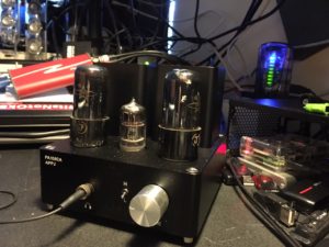
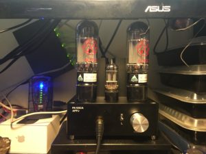
Having recently completed the mods to my Bravo v2 hybrid tube amp, I felt the itch to mod the headphone amp I use at home, my Gemtune APPJ PA1502A. This amp provides full tube amplification instead of a hybrid design. I picked this amp from Massdrop at a very reasonable price. Unlike the Bravo, this promised to be an amp that did not need mods, only a good set of tubes to bring it to life. Stock the sound was crystal clear, but too flat in the lower ends for me, expanding the bass would be a priority. Upgrading to better tubes made a world of difference. Once I had broken in the new set of tubes I decide to perform a small mod and upgrade the inter-stage coupling caps, this sound deepen the bass even further.

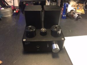
Stock APPJ PA1502A

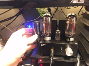
Stock Gemtune APPJ PA1502A with the original tubes

Rolling New Tubes

This is the easiest mod that one can perform, replacing the tubes with better ones. Replace the 6N4 with a 12AX7 or 5751 type tube. I’m currently running a Sovtek 5751. Next the two 6P6Ps should be replaced with a pair of good quality 6V6s or 6L6s. I have a set of Tung-Sol 6V6GTs and a set of JJ Electronics 6L6GCs that I have tried in the amp. Both sound great, but I am a fan of the 6L6s. The 6L6 is both physically larger and a more electronically demanding tube, but one that the circuit specs state it can handle.  They will put out more heat, so if that’s a concern, stick with the 6V6.

The 6L6GC is a much larger tube than the 6P6P

The 6L6GC is a much larger tube than the 6P6P

I have also added tube risers. The stock tube connectors are only secured through solder and I had some fear of damaging them when swapping tubes. I added tube risers that take the brunt of the force when swapping tubes around.

Tube risers

Tube risers

Once the tubes were swapped and broken in I was very happy. Break in time seems to be very important for amps such as this. When I first got the amp I had to run it for at least a few hours before it started to sound right. Once I swapped the tubes and let it warm up for another few hours the sound was richer, bass was deeper, and still crystal clear. I’ve read that these amps and any new tubes need to be burned in for at least 48 hours, so expect slight improvements until burn in is complete.

Replacing the Inter-Stage Coupling Capacitors

This is a very simple mod, one that should increase the deepness of the bass, making the amp a bit more lively. I debated performing this mod as I was already very happy with the amp and the 6L6 mod fixed the flatness from the lower end. The inter-stage coupling circuit for this amp uses two 0.1uF 400V ceramic capacitors, these can be replaced with 0.47uF 400V capacitors.

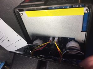
First we need to remove the four screws holding the top of the amp. This top also contains the transformers, which can easily be detached from the main circuit board through four plugs

Top

Remove the four top screws to expose the top of the board. The plugs for the transformed will unplug easily.

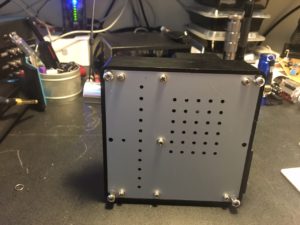
Next we need to remove the four feet and the six outer screws holding the bottom plate on. On my amp there is a seventh screw, but it is screw to a post that is screw into nothing.

Bottom

The four feet and six outer screws need to be removed to access the bottom

Bottom of the APPJ PA1502A

The bottom of the amp, exposing the two ceramic capacitors to swap

Next I de-soldered the two ceramic capacitors. The below images show the solder points that I hit with my de-soldering iron .

IMG_8091 IMG_8094 IMG_8090 IMG_8088

Finally the new capacitors were soldered onto the board and the board reassembled and tested.

Inter-stage capacitor upgrade complete

Inter-stage capacitor upgrade complete. White ceramic 0.1uF 400V caps replaced with orange  0.47uF 400V caps.

Next I powered it up and verified that I didn’t short anything out before reassembling.

IMG_8097 IMG_8096

No fire, no sparks, the audio is clear, and my headphones sound great, time to reassemble and put back where it belongs.

Gemtune APPJ PA1502A in use

Gemtune APPJ PA1502A in use back where it belongs

Afterthoughts

I spoil myself with this amp, the clarity of the audio is almost startling. I have the amp paired up with a pair of Beyerdynamic DT990 600 ohm headphones. Not a combination that is bass heavy without the mods, but one that will provide some serious HD audio. I let my boyfriend listen to the amp while it was burning it, his eyes told me all I needed to know. Afterwards he described the experience as disturbingly HD, kinda like the first time watching a HD or 48fps movie, almost too lifelike. Goal achieved ^__^

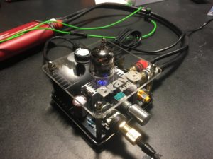
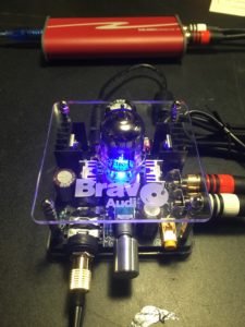
In March I picked up one of these little Bravo Audio V2 class A hybrid tube amps on sale. This neat little headphone amp uses a 12AU7 vacuum tube to provide that ‘warmth’. There are plenty of articles, reviews, and forum posts that go into the details of what this little amp is capable of, plus it’s moddable. I bought it because I love tube audio and I could have some fun and tweak it.

 Bravo v2 Original

First Impressions

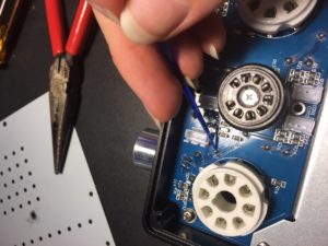
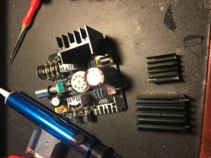
This amp looks like it was designed to be modded, but the reality is that the PCB is rather fragile. Traces are prone to falling off, especially if you use a soldering iron that is too hot. The first thing I had to do to mine was retin it with fresh high quality solder. It looked like it had been soldered with J-B Weld, plus it cleared up the audio. Once that was done I started swapping different 12AU7 tubes from my collection, eventually decided on an Electro-Harmonix for daily use. The stock tube didn’t sound bad, but the new EH 12AU7A seemed to handle the highs and lows better. I tested a vintage clear-top RCA, but the low ends sounded muddled, it is possible that the tube is failing. I proceeded to use the amp in this configuration at my job.

 Bravo v2 Original

Time To Perform the Mods – Easy First

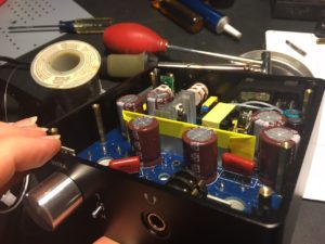
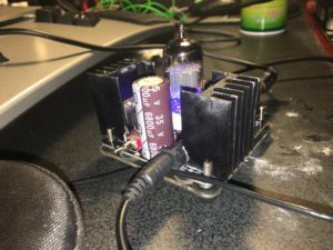
The most common mods are component upgrades. Replace the electrolytic capacitors with higher quality 35V caps. Interestingly enough, when I was replacing the caps, I saw that the circuit board states that these should be 35V. This is an easy mod, there are only three caps, 1 – 6800uF, 2 – 1000uF.

New power cap

Final result with new power cap

Upgrade the MOSFETs – Hard Next

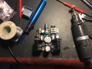
Replacing the IRF630Ns with almost any of the IRF510-530 series will improve the soundstage and roll-off. I opted to replace mine with the IRF530N, an improved version of the IRF510. This mod is not as easy as the heat sinks for the MOSFETs should be replaced with larger ones to handle the increased power consumption and thus heat generation. On my board I had to drill out the old heatsink mounts, and some of these mounts do go near traces. I do not have precision tools.

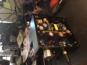
Work in progress on the amp

Work in progress on the amp

In progress fitting of the heatsinks

In progress fitting of the heatsinks

New IRL530N MOSFETs

New IRL530N MOSFETs

The Final Results

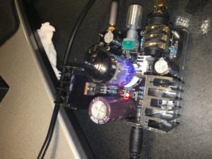
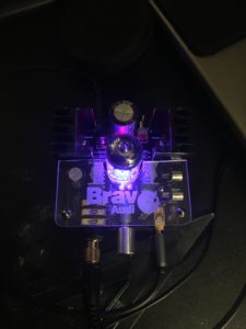
I have been using the amp daily for the past week. It sounds so much better now, a noticeable improvement. I consider the amp and the mods a worthwhile improvement.

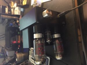
The final result

The final result

Approximately one year ago I switched my Aerogarden from the stock fluorescent bulbs to using LEDs and to using a three part nutrient regimen.

LED Bulb Update

The stock bulbs had to be replaced every 3-6 months for one of two reasons. One, the stock bulbs will dim with age, the Aerogarden flashes a reminder to replace the bulbs when it thinks they’re getting old. Two, the stock bulbs burn out within 3-6 months, thus I always kept extra bulbs on hand. The LEDs show no signs of dimming and none have burned out, making them a very worth while investment.

The only fear I had switching to LEDs was that they didn’t put out as much light, or that the light beam wasn’t as wide. I grow potted plants around the Aerogarden, utilizing the light spillage for less light hungry plants. To make up for the loss I added two full spectrum light strips to my grow shelf. In addition to the basil, I regrow kitchen scraps. Right now that includes a small amount of ginger, lettuce, and green onions.

Three Part Nutrient Update

I love using the three part nutrients. Every two weeks I pull out the relatively large bottles, 1 quart each, and use roughly 1 teaspoon from each. These nutrients should last me years, especially stored correctly. Quart by quart, the three part nutrients cost half as much as the premix. Besides the cost saving I tweak ratios depending on if these are fresh seeds, established plants, or if it’s time to force them to flower. While I’m still learning how to grow salad greens and veggies in the Aerogarden, I have had much better success with the three part nutrient system. The basil has a habit of overrunning the Aerogarden if I don’t attend to it regularly, it will prevent the slower growing plants from being able to establish themselves.

A couple of years ago I discovered the Odroid, a single board computer similar to the Raspberry Pi, only powerful. I invested in an Odroid U3 and various accessories. While I never full utilized all that I have available for it, the system has been invaluable over the years. I have run various servers, controlled usb cryptocurrency miners, ambient atmospheric conditions, and as a airplay interface to my stereo. I have since added two more Odroids to my collection.

Odroid XU4

The high performance NAS. Built into the rather spiffy CloudShell case with LCD and SATA interface, this is the most powerful Odroid available at the time of this being published. Octocore running at 2Ghz with 2GB/ram, 2 USB 3.0 ports, 1 USB 2.0 port, Gigabit Ethernet, a 32GB eMMC card, and some other spiffy technical specs available on the manufacturer website.

Since I was constructing a NAS I opted for the CloudShell case. Set it up running Raspbian with a 120GB internal SSD, and two external 4TB external USB 3.0 drives. From my quad-core desktop over gigabit, to the Odroid’s internal SSD I will achieve 60MB/sec transfer. Previously I used an Raspberry Pi B+ as the NAS server, it was hella slow. This is an amazing upgrade.

Odroid C1+

Purchased with the sole purpose of being a Hifi audio player. I added the C1+ specific Hifi shield, also available from Hardkernel, for audiophile grade audio into my Outlaw (they make good quality stuff for the $$$) preamp. Installed the Volumio audio player distribution. While the distro has some bugs, it is working extremely well for me, possibly the best remotely controllable media player I’ve used on a Linux system. The combination of the two components, the Volumio distro, plus the amps, creates an easy to use interface with a beautiful clear sound.

Odroid U3

The U3 is now at the beginning stages of a new project, a Gentoo installation. In additional to the on-board eMMC, there is an external ssd. This is my primary experimental system.

Why Gentoo?

Gentoo is my preferred Linux distribution.  I’m a fan of customization. Due to some of my personality quarks (some might say disabilities), most standard workflows slow me down. I have spent eleven years tweaking and customizing my main Gentoo desktop install and interface. Gentoo allows me to easily setup the system exactly the way I work best.


Continued in Part 2 (to be completed and published middle of October)

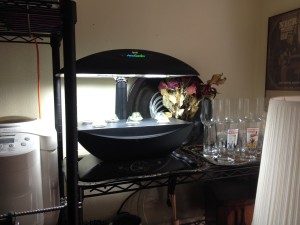
Aerogarden on a shelf

The Aerogarden fits nicely into a corner of a room.

The Aerogarden is Miracle Gro’s attempt at bringing hydroponics to the masses. Last year I picked up an Aerogarden 7, which is a mid range 7 pod, unit. Fresh out of the box it comes with the unit, two fluorescent bulbs, an herb kit, and nutrients.

It is easy to buy pod kits, plus you can buy pod refills that allow you to use your own seeds. I started using the refills and purchased my seeds separately. I started growing basil years ago, my basils are now 5th generation and it’s looking like 6th generation seeds will be produced soon.

Nutrients

By following the instructions and cleaning the water out every time one adds fresh nutrients, a stock kit will grow most herbs and maybe even some veg fine. Why? I may be wrong, but I have read that Miracle Gro nutrients tend to be a bit heavier in some than in others, which triggers imbalances. I had trouble growing veggies and cilantro, while the basil grew great.

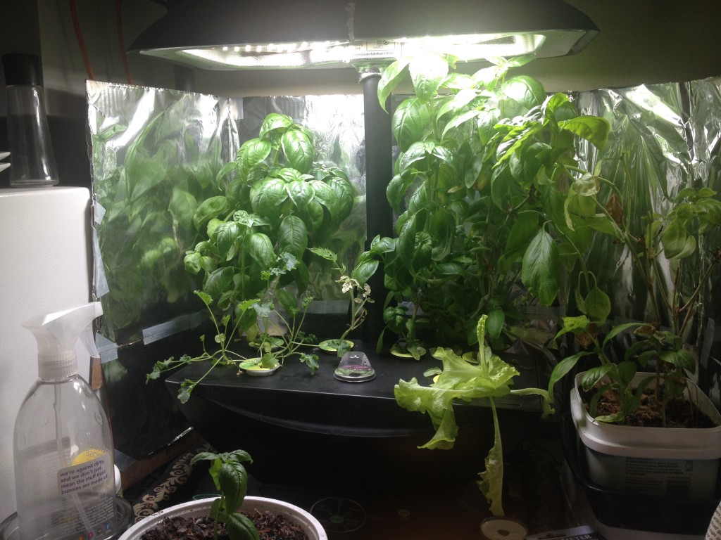
A good two or three part nutrient system along with the tools to measure water quality and ph balance will maximize the Aerogarden’s potential. Since switching to a three part system I was able to start growing a mix of basils, kale, salad greens, and a small pepper plant. I have been using filtered tap water which is around 140ppm, the standard tap water reads around 180ppm, hard water. The lower the ppm the better.

My Aerogarden 7 growing a mix of herbs and greens

My Aerogarden 7 growing a mix of herbs and greens, using a three part nutrient system and filtered water.


Bulbs

The Aerogarden 7 with the LED light upgrade.

The Aerogarden 7 with the LED light upgrade.

The stock bulbs will put out sufficient light, but they have a limited life span, roughly 3-6 months per bulb, and are fluorescent, using around 25 watts each. The bulbs put out enough light that I’ve even managed to grow plants in pots that sit around the Aerogarden. The major disadvantage is that the bulbs do put out a lot of heat and can burn leaves that grow too close. This can be worked around by installing LED lights from a 3rd party vendor. The LED lights use 10 watts each. The LED lights have been reported to put out slightly less lumens, but they are full spectrum and my garden is still growing well. I’ve only been running them for a couple months, but no issues so far.

Water Reservoir

The base, where the water goes, is a very simple aeroponics setup. It has a built in aerator similar to the air bubbles for fish tanks. Newer models use a different setup, but this works well. If the aerator in the Aerogarden has fail or if you feel that the aerator isn’t circulating the water well enough, it can be replaced or supplemented with one built for a fish tank. I check to make sure mine is clear each time I clean my reservoir out.

Control Circuit

The electronics themselves use a simple control circuit that controls at least three timers, one timer triggers the light relay, another timer triggers the aerator relay, finally there is a timer for the ‘Add Nutrients’ light. The circuit also integrates a simple low water sensor.  This entire circuit could be easily replaced with a raspberry pi or arduino for custom schedules. It’s something I’m considering doing in the future.